
Electromagnetic calculation of 2MW direct-drive permanent magnet generator
Idea: Based on the 2MW permanent magnet generator data provided in the article ” An Engineering Design of 2MW Direct-drive permanent-magnet Wind-power Generation System ” , the electromagnetic scheme is deduced using Speed software, and then electromagnetic calculations are performed using Flux . Finally, some parameters calculated by the two electromagnetic software are compared and analyzed.
Step 1.
The data of 2MW permanent magnet generator provided in the article ” An Engineering Design of 2MW Direct-drive permanent-magnet Wind-power Generation System ” are as follows:
Step 2.
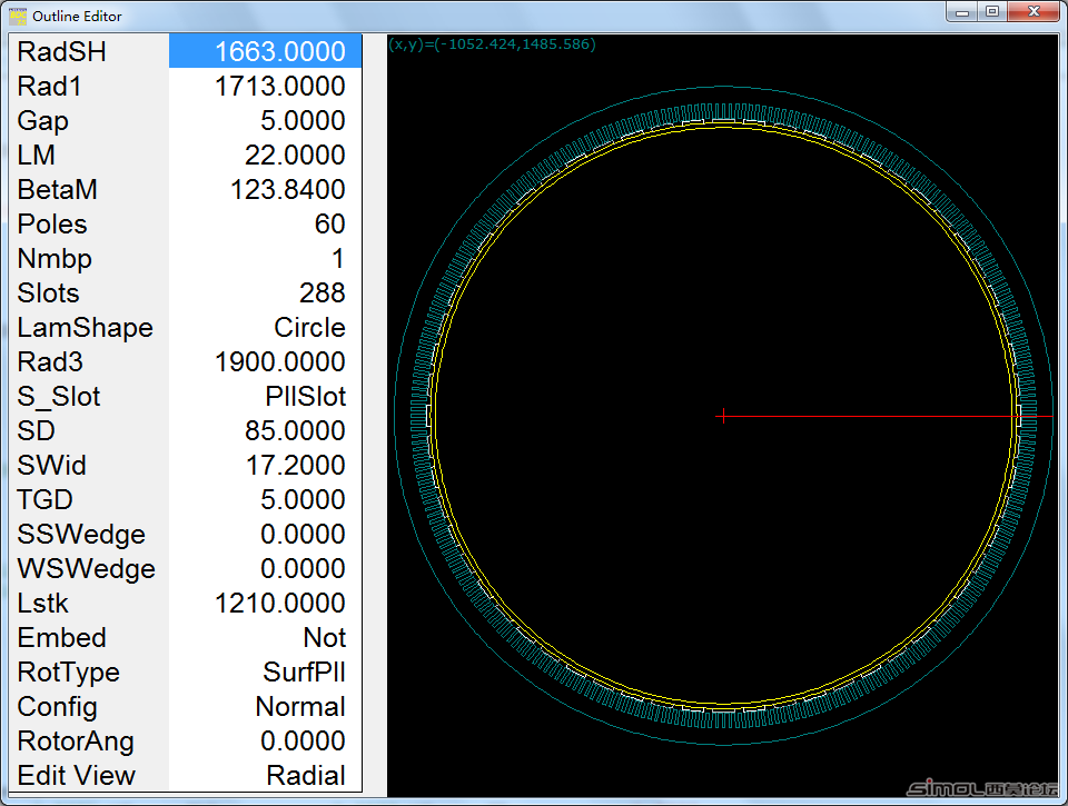
The electromagnetic scheme is calculated based on SPEED as follows:
The main calculations are the number of coil turns and the number of parallel branches. In this example, the number of slots per pole and per phase of the motor is 1 3/5 . According to the symmetry condition of the winding of the fractional slot, the maximum number of parallel branches of this motor is amax=12 . The actual number of branches a can be less than amax , but amax must be an integer multiple of a . Because the length of the core is given in this example, the main thing in SPEED is to adjust the number of coil turns and parallel branches to meet the requirements of the back electromotive force. If fine-tuning is required, you can consider increasing or decreasing the winding factor. When the number of coil turns is determined, the wire gauge can be roughly determined according to the relevant insulation specifications and current density. Finally, adjust the power angle to meet the power requirements. In the entire adjustment process, the initial value of the power angle must be given based on experience.
Motor structure model:
Winding type:
Winding pitch: 4 ; Coil turns: 8 ; Wire gauge: 2 (4 x 8 ); Number of parallel branches: 12

Result data (not skewed):

Current, back EMF and torque waveforms:

Step 3.
Using Flux for electromagnetic calculations:
Due to time constraints, only no-load calculations are performed here. Friends who are interested can perform three-phase short-circuit and demagnetization tests, load calculations, cogging torque and skew calculations.
To build a model in FLUX , you only need to create a unit motor. In this example, the unit motor has 5 poles and 24 slots. Set the face region of the coil according to the winding form calculated in SPEED .
Motor model and mesh generation:

No-load magnetic field distribution:

No-load magnetic flux density distribution:

No-load back EMF and FFT :

The effective value of the fundamental phase voltage is 369V . Due to the use of pole chamfering, the voltage waveform has good sinusoidal properties and very small harmonics.
No-load air gap flux density and FFT :

The peak value of the fundamental wave of the air gap magnetic density is 0.8954 T
Step 4.
Comparison of some parameters in no-load calculation:
From the above data, it can be seen that the calculation results of the two major electromagnetic software SPEED and FLUX are basically the same. In this case, the cause of the error (excluding the calculation differences between the two software themselves) is mainly the size of the magnetic pole chamfer in the FLUX modeling. In addition, when using these two major electromagnetic software for calculation, there are differences in the performance of the materials used for the stator and rotor.
Conclusion:
The 2MW electromagnetic scheme calculated by SPEED is feasible after verification by FLUX calculation, but it is not the only one. By comparing the calculated values of SPEED and FLUX , it can be seen that the calculation results of the two are basically the same. Since SPEED ‘s calculation speed is very fast, it can be considered to use SPEED when making preliminary motor scheme design . When the electromagnetic scheme is determined, the powerful post-processing of FLUX can be used to make electromagnetic calculation reports.


